Microbial Desalination is a technology to remove salt ions from saline water (deionize saline water). Driven by electric current (electric potential difference) generated by the metabolic activity of exoelectrogenic microorganisms, i.e. driven by a bio-electric potential difference, ions are transported through ion selective membranes, thus generating an ion-enriched stream (brine) and an ion-depleted stream (desalinated water). Ion transport is effected in proportion to the electric current being generated by these microorganisms [1,2,3].
1. Technical Description
The Basics – Separation Principle and Operating Mechanism
An exoelectrogenic microorganism is a microorganism that has the ability to transfer electrons extracellularly. Exoelectrogenic microorganisms are also referred to as “exoelectrogens”, “electrochemically active bacteria”, “anode respiring bacteria” and “electricigens” [4]. A known species of exoelectrogens is, e.g., Geobacter sulfurreducens.
In a Microbial Desalination Cell (MDC) exoelectrogenic microorganisms serve to generate electric current (electrons) from oxidation of organic matter present, e.g., in wastewater [3] or in artificially created nutritious solutions. The electric potential difference between anode and cathode generated by the metabolic activity of these microorganisms is the driving force for desalination in an MDC. It is used to induce ion transport through ion exchange membranes [2,5], thus desalinating water.
Therefore, the driving force of desalination in MDC may be – more precisely – referred to as a “bio-electric” potential difference. The fundamental separation principle to separate ions from water in MDC is the capability of ions to move selectively according to their charge.
MDC is in nature similar to Electrodialysis (ED), yet different from ED because it does not require external electricity [1]. Instead, energy is provided by the exoelectrogenic microorganisms, being an integral part of the MDC.
It goes without saying that the particular attraction and benefit of MDC lies in the fact that MDC allows desalination without external electrical energy input and without the need of high feed pressure. In consideration of the relevance of energy cost in desalination, a desalination technology like MDC, which does not consume more energy than generated by itself, must be of particular interest.
A further benefit of Microbial Desalination Technology is that it combines at least two simultaneous functions: electrical energy production and desalination. Depending on design, it may also take up a third function. If, for example, wastewater is used to feed the MDC and the organics contained therein serve as food source for the microorganisms, the MDC can even achieve three functions simultaneously: energy production, desalination and wastewater treatment.
Process Description
The first proof of concept of MDC was demonstrated in 2009 by a 3-chamber configuration [1, 6, 7]. This basic Microbial Desalination Cell resembles a fuel cell, containing an anode and a cathode, between which a pair of ion selective membranes is inserted. Fig. 1 depicts the basic design of a Microbial Desalination Cell (MDC).
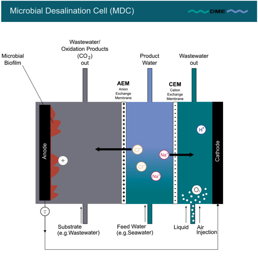
Fig. 1: MDC – basic design
It consists of three chambers:
1. the anode chamber with an anion exchange membrane (AEM). Next to the anode a film of exoelectrogenic microorganisms is attached as a kind of biofilm. The chamber is typically filled with a liquid (e.g. wastewater) which contains nutrition for the exoelectrogenic microorganisms. These exoelectrogenic microorganisms oxidise organic matter, and, in doing so, release protons and electrons.
2. the cathode chamber with a cation exchange membrane (CEM) positioned next to the cathode. This chamber, in which the electrons transferred from the anode are consumed by a chemical reduction reaction (as described below), is typically filled with a liquid that enhances cathode performance (e.g. water + air injection).
3. the middle chamber between the two ion exchange membranes (AEM and CEM) is filled with feed water to be desalinated [1].
Process Description MDC
The MDC process (here with an air-cathode) is depicted in the following sequence (Fig. 2 A – C)

Fig. 2 A: MDC process - anode chamber Fig. 2 B: MDC process - cathode chamber Fig. 2 C: DC process - resulting stage
Exoelectrogenic microorganisms on the anode oxidise organic matter fed into the anode chamber. In doing so, they release protons (H+) and electrons (e-) (see Fig. 2 A). The following equation represents the oxidation reaction at the anode [8]:
(CH2O)n + nH2O → nCO2 + 4 ne- + 4nH+
The electrons (e-) leave the anode chamber and are transferred as electric current via external wire to the cathode. Protons (H+) cannot leave the anode chamber, as they are rejected on the anion exchange membrane (AEM). The surplus of positive charge in the anode chamber resulting from protons (H+) produced, however, desires balancing. The only source of balancing charge is drawing negatively charged ions (Cl-) through the AEM from the middle chamber into the anode chamber (see Fig. 2 A).
Simultaneously, in the cathode chamber, electrons (e-) are received as electric current (see Fig. 2 B). There they combine, e.g., with the oxygen provided by an air-cathode or by oxygen injection into the cathode chamber. They combine as well with the protons (H+) drawn from the liquid in the cathode chamber (chemical reduction reaction) to form H2O. The following equation represents the reduction reaction at the cathode [8]:
O2 + 4 ne- + 4nH+ → 2 H2O
The extraction of protons required for the formation of H2O leaves a deficit of positive charge in the cathode chamber which can only be replenished by attracting positively charged ions (Na+) from the middle chamber. As only positively charged ions can pass the cation exchange membrane (CEM), Na+ ions cross the CEM and replenish the protons consumed in the formation of H2O (see Fig. 2 B).
As a result (see Fig. 2 C), the feed water in the middle chamber is depleted of salt ions, i.e. desalted. Thus, the generation of electric current through oxidation activity of exoelectrogenic microorganisms induces an electric potential difference between anode and cathode, which in turn induces a selective ion transfer through the AEM and CEM, thereby depleting the feed water stream from salt ions.
This depletion of ions in the middle chamber results in water desalination without any water pressurisation or use of draw solutions or externally supplied electrical energy. Instead, energy is generated while water is desalinated, and, as the case may be, organic matter is removed from wastewater while being metabolised by the microorganisms ́ activity in the anode chamber [1, 2, 5, 6, 8, 9, 10].
MDC Process Peculiarities
- MDC operation does not require electrical energy input and no elevated pressure level like Reverse Osmosis (RO) [1].
- MDC requires, however, specific exoelectrogenic microorganisms which themselves need a continuous supply of a nutritious substrate for their metabolic work. MDC also requires an aerobic environment on the cathode side, which may be achieved by oxygen injection or otherwise procuring an aerobic water environment in the cathode chamber [6,8].
- The supply of microorganism substrate may be secured by connecting the MDC to a wastewater plant effluent to benefit additionally from wastewater treatment as a co-performing element of the MDC process.
- MDC may constitute a (limited) barrier against bacteria, viruses and other microbes as the pore sizes of ion exchange membranes used will be in the range of 1 nm (about 350 Dalton), i.e. considerably smaller than the size of viruses and bacteria [2]. However, contradicting this opinion, it should be noted that not the complete volume flow to be desalinated needs to pass through the ion exchange membranes, thus limiting the true sanitary impact of MDC technology.
- Due to yet missing field experience, it is not known to what extent MDC modules might need intermittent cleaning during operation or to what extent they might need to be preserved against biological growth in case of shut down for a prolonged period.
For further requirements concerning MDC plant layout, please also refer to Section 2 (Plant Design) hereinafter.
Motivation of Use
In consideration of the remarkable energy cost of other desalination technologies, MDC has been developed to overcome this drawback [1]. The idea to desalinate water without consumption of energy is certainly fascinating. It requires, however, the integration of another process element (energy production by exoelectrogens from digesting organic matter). At this point of time, MDC has a unique potential to emerge as a technology to perform three fundamental tasks simultaneously: (seawater) desalination, electric energy generation and wastewater treatment [8].
Technical Variations
MDC Design Variation and Optimisation
The basic MDC cell, incorporating three chambers forming one stack, is illustrated in Fig. 1 above.
While this type of model will be indispensable for lab purposes, multiple stack designs are desirable to increase desalination volume and to decrease manufacturing cost. Multiple stack structuring is achieved by repetitive addition of AEM and CEM membrane pairs to the module as illustrated in Fig. 3 below, thus creating repeating desalting and concentration cells [7].
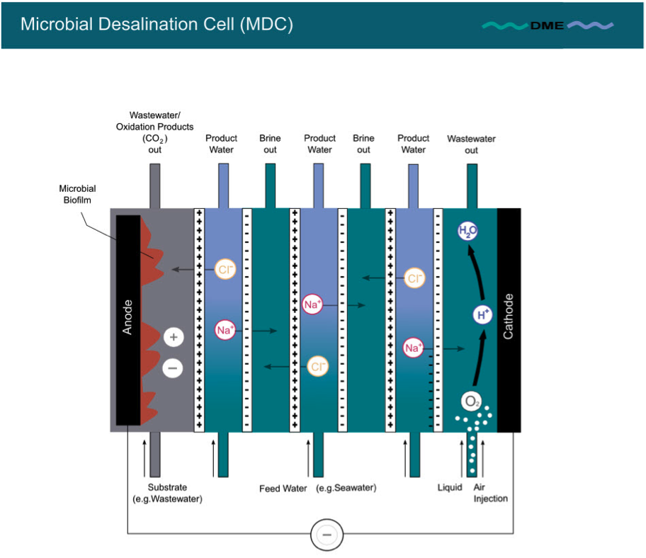
Fig. 3: Stack structure of MDC
Stacking increases the magnitude of ionic separation. In a stacked MDC, a single electron transfer from anode to cathode can separate as many ion pairs as the number of repeated AEM and CEM membrane pairs. For instance, in a 3 cell pair stack, a single electron transfer separates 3 pairs or mono-valent cations and anions by use of an (ideal perm-selective) ion exchange membranes [2,8].
Other basic design considerations in MDC technology relate to:
a) sizing of the anode surface in relation to cathode surface, whereby the cathode appears to require larger surfaces or a boost in speed of performance due to the relatively low speed of chemical reduction performance of the cathode;
b) sizing of the anode chamber volume versus the desalination chamber and cathode chamber volume. It appears that anode chambers require a significantly larger volume than the other chambers;
c) choosing optimum electrode materials, particularly for the cathode due to its slow chemical conversion characteristics. In this context, improved material choice for the purpose of elevated current densities per m2 of electrode surface is of particular interest [11];
d) choosing optimal electrode materials to improve electrode stability and lifetime.
MDC Operational Variations & Performance Optimisation
As MDC works with organic matter and may fulfil three tasks at once, there are numerous parameters to work on simultaneously. Research is on its way to study variations of parameters and analyse patterns of dependence. Yet, as MDC technology is relatively young, most current knowledge is based on lab tests. To the best of the author ́s knowledge, MDC field experience is still missing. Therefore, the following aspects of operation are of indicative nature and observations may yet not all be fully studied. Particular complexities are apparent when applying MDC:
- A particular optimisation complexity of MDC is to understand the convergence or divergence of achieving three optimisation targets simultaneously, i.e. maximum electrical power generation, highest desalination volume or highest degree of desalination and highest reduction of organic matter.
- A further particular complexity of MDC is to work with a multitude of parameters that may be altered and to understand their relative alteration contribution on the desired performance targets, both technically and commercially.
Some operational aspects, however, have been researched already in some detail and appear to have influence on MDC performance and its optimisation:
- pH value variation between anode and cathode chamber: As the desalination cycles proceed, the pH value in the anode chamber decreases due to proton accumulation by microbial respiration and increases in the cathode chamber due to hydroxide accumulation by oxygen reduction [8]. Therefore, decrease in pH value is a major challenge for MDC operation [2]. It adversely affects both, the microbial activity and growth in the anode chamber and the chemical reduction efficiency of electron acceptors (O2) in the cathode chamber. Such pH imbalance may be alleviated by increasing the anodic chamber volume or by adding acid or base. The addition of acid or base as well as the addition of a phosphorous buffer solution do not appear feasible with respect to cost and environmental concerns. Furthermore, frequent exchange of the anolyte solution, i.e. the fluid contained in the anode chamber, has proven beneficial [6].
A recirculation of a fraction of the anolyte to the cathode chamber and from there back to the anode chamber, a so-called recirculation microbial cell (rMDC) design has been investigated to overcome the pH problem. As this solution generates new issues (e.g. transfer of O2 to the anode side), an economic and sustainable method of controlling the pH remains an urgent development need in MDC technology [6, 8].
- Impact of Internal (Ohmic) Resistance: A decrease in conductivity of the saline feed water increases the internal resistance (IR), i.e. the resistance within the MDC cell and thus decreases the overall electric cell potential of the MDC. As a countermeasure, membrane distance may be increased to decrease IR [1, 6].
Also, stacking of MDC improves the desalination rate, but also leads to a higher electric potential loss due to an increase in IR from increased stacking [2, 6].
MDCs operated with lower Hydraulic Retention Time (HRT), i.e. the period until exchange of the anolyte, shows lower IR [6].
- Impact of External (Ohmic) Resistance:
The external resistance (ER), i.e. resistance in the wire between anode and cathode, is of importance for the desalination efficiency. At lower ER values (e.g. 10 Ohm instead of 100 Ohm), the electrical current density (in theory) is higher and thus increases the rate of desalination. In other words, more Total Dissolved Solids (TDS) is removed with lower ER (i.e. higher electrical current density) [6].
- Batch vs. continuous MDC operation:
In batch mode, the performance of MDCs decreases with time as the internal resistance (IR) increases due to the lowering of electrolyte conductivity in the desalination chamber. Cyclic batch mode, or even better, continuous mode operation can be the optimum choice for practical operations because it reduces total capital cost and facilitates control of decisive parameters such as pH and substrate concentration [6].
- Variation of Hydraulic Retention Time (HRT):
MDCs operated with lower HRT of anolyte solution exhibit lower Internal Resistance (IR) [6, 12].
- Scaling of CEM membranes and fouling of AEM membranes:
Depending on the salinity of the water to be desalinated, CEM scaling is of significant importance for MDC performance [6, 7]. A complete prevention of membrane scaling appears impossible; however, use of an oxygen cathode with acidified water may alleviate scaling [7]. Membrane fouling may be observed on AEM due to biofilm growth [5, 6]. Chosen ion exchange membranes also differ considerably in pore size, degree of organic matter.
- Choice of exoelectronic microorganisms:
It will be obvious that the metabolism of microorganisms differs from species to species. Therefore, study of MDC performance in terms of electron generation capabilities and degradation potential of organic matter are relevant areas of study [13].
Differences to and Similarities with other Relevant Technologies
The MDC process has great similarity with Electrodialysis (ED), but in the case of ED external electrical energy is used to provide energy for the separation of ionic species.
With respect to Reverse Osmosis (RO), MDC does not need pressure elevation to high levels.
However, different to all other desalination technologies, MDC integrates bio-electrochemical energy production with desalination and water treatment, i.e. performs multiple functions. Due to this specialty, a one to one comparison of MDC to other (pure) desalination technologies is not advisable, also because the technologies have different outputs.
A further comparison of benefits and drawbacks vis à vis other desalination technologies appears premature due to the fact that MDC does not yet have practical field experience for realistic comparison.
2. Plant Design
Process Requirements
A full plant arrangement may - apart from the core desalination unit (MDC) - also require the following:
- A feed pump for supplying pretreatment and desalination unit with feed water is needed.
- Appropriate pretreatment to limit scaling and fouling of MDC desalination chambers with elevated scaling risk seems to be necessary.
- Appropriate process treatment to reduce scaling potential, particularly on CEM membranes, appears necessary.
- Depending on finally preferred channel width of the desalination chamber (e.g. 0.3 – 1.5 cm) and the preferential widths of anode and cathode chambers, the MDC cell requires some specific degree of protection against blocking by particles which may differ for the three chambers into which fluids are fed. Particle filters in the range of a few microns could serve as the last step of pretreatment for the feed water to be desalinated, for the influent water from waste water treatment process to be fed to the anode chamber as well as for the liquid in the cathode chamber [6].
- Depending on application, the feed water streams may need further individual pretreatment to protect the micron filtration systems suggested beforehand (e.g. further pre-filtration step at larger mesh size).
- Depending on Total Suspended Solids and Total Organic Carbon (TSS/TOC) loading of the feed water, further pretreatment to reduce TSS/TOC volume may be required for the feed water to be desalinated; also, the TSS/TOC levels of the anolyte and catholyte need separate specification.
- In applications with elevated scaling risk, appropriate process treatment to reduce scaling potential, particularly on CEM membranes, appears necessary.
- Compressed air injection may be required for optimised cathode performance.
- Cleaning-in-Place (CIP) unit (possibly with neutralisation) for cleaning of MDC modules may be a requirement.
- A wastewater disposal facility to allow for occasional CIP wastewater discharge (if in fact required), intermittent filter backwash water discharge and sludge discharge for used up anolyte discharge may be needed.
- Depending on application, posttreatment of the desalinated water may be required.
MDC Plant Layout
Due to the advantage of being able to build MDC units module based, MDC plants are scalable in size [3]. Fig. 4 illustrates an exemplary MDC system arrangement.

Fig. 4: Exemplary MDC system arrangement (in conjunction with wastewater treatment plant)
3. Feed Water
1. Different from other desalination technologies, three feed streams need to be considered: the feed flow of the water to be desalinated, the wastewater treatment flow connecting to the anode chamber and the water flow feeding the cathode chamber.
2. Without any field experience so far, it is premature to take a judgement on the potential techno-commercial limitations of MDC due to the level of feed water salinity of the water to be desalinated.
3. As far as other pretreatment requirements are concerned, please refer to the points mentioned hereinabove.
4. Temperatures may be limited to AEM and CEM operational limits, possibly also to anode and cathode temperature limitations.
5. For general guidance purpose, the following Table 1 characterises general MDC feed water limits for the water to be desalinated.
| Feed Water Salinity | Technically feasible | Now in Use for Desalination | Potentially for techno-commercial Viability for the Future |
|
> 100,000 ppm |
|||
|
50,000 – 10,0000 ppm |
|||
|
10,000 – 50,000 ppm |
X | X | |
|
1,000 – 10,000 ppm |
X | X | |
|
< 1,000 ppm |
X | X |
Table 1: Stage of development of MDC technology in relation to water salinity [2, 6]
Because of the comparatively low desalination efficiency for high-salinity water, one potential application of MDC technology could be brackish water desalination [6].
4. Desalinated Water & Brine
Without any field experience so far, it is premature to characterise desalinated water and discharge flows in volume or quality other than recognising their existence as depicted in Fig. 4 above.
5. Data and Information
In the absence of field test results so far, it does not appear appropriate to take assumptions on data and information under this chapter.
6. Preferred Use
The techno-commercial feasibility of MDC has not yet been demonstrated in the field. Therefore, the preferred uses listed below are of indicative nature only:
1. Seawater desalination
Lab tests vary widely < [1,9] but show up to 99 % salinity removal depending on Hydraulic Retention Time (HRT) [6].
2. Brackish water desalination
An obstacle of low salinity desalination by MDC is that the low conductivity increases the internal resistance on the MDC. This disadvantage may be overcome by adding an ion exchange resin to the desalination chamber. Also, salt removal from the desalination channel increases the salinity of the anolyte which may negatively affect the activity level of the microbial community in the anode chamber [6].
3. Water softening
Up to 90 % hardness removal has been demonstrated in lab tests [6].
4. Ground water remediation (in particular nitrate removal) may be a feasible application [6].
5. Simultaneous desalination, wastewater treatment and hydrogen production (while adding energy to an MDC process in a modified “Microbial Electrolysis and Desalination Cell”) may be a desired application [6].
7. Environmental Impact
With respect to energy consumption the MDC may be considered a sustainable process, as it is based on a renewable primary energy source. However, research has not yet demonstrated dependable field test results to judge environmental impacts of MDC professionally.
Also, and as mentioned above, it appears likely from lab test demonstrations that MDC will not be able to survive without countering measures of scaling and fouling. In this respect dosing of chemical additives is very likely to be required to maintain MDC performance.
8. Stage of Maturity
Table 2 summarises MDC technology with respect to the technology ́s stage of maturity.
| 1 | 2 | 3 | 4 | 5 |
| Basic R&D |
Prototyping/ |
Field Tests/ Demonstration |
Commercialization (up to 7 years) | Use/Established (more than 7 years) |
| X |
Table 2: Stage of maturity of MDC technology
9. Further Developments
These are the challenges for improvement in MDC:
1. Primary target for MDC will be to reach field test level to measure and benchmark real performance and to generate cost reduction from exploiting scale effects [14].
2. Scaling up of MDC devices will be a further target. While primary tests have been performed with desalination chambers of 3 ml, larger desalination chambers (15 litres) are subject of more recent investigation. Simultaneously the anode chamber has been increased from 27 ml to 60 litres. The largest MDC (total volume of 105 litres) has achieved an electricity generation of 2,000 mA and a salt removal rate of 9.2 kg/m3/d [6, 14].
3. For developing more breadth and depth in applications, it is envisioned that MDC may be used as pretreatment of RO systems to reduce the overall cost of desalination [6]. In particular, the energy produced in MDC operation could be used to run downstream RO or Electrodeionisation (EDI) plants.
4. Major challenges for the development of MDC as a desalination technology are:
- managing pH variations;
- managing scaling and fouling, in particular cathode scaling;
- controlling internal and external resistance;
- improving anode and cathode materials and longevity;
- improving exoelectrogenic bacteria performance.
10. References
[1] Cao, Xiaoxin; Huang, Xia; Liang, Peng; Xiao, Kang; Zhou, Yingjun; Zhang, Xiaoyuan; Logan, Bruce E.: A New Method of Water Desalination Using Microbial Desalination Cells. Environmental Science & Technology 43 (2009), pp. 7148-7152.
[2] Kim, Younggy; Logan, Bruce E.: Microbial desalination cells for energy production and desalination. Desalination 308 (2013), pp. 122-130.
[3] Subramani, Arun; Jacangelo, Koseph G.: Emerging desalination technologies for water treatment: A critical review. Water Research 75 (2015), pp. 164-187.
[4] Logan, Bruce: Exoelectrogenic bacteria that power fuel cells. Nature Reviews Microbiology 7 (2009), pp. 375-383.
[5] Wang, Heming; Ren, Zhiong Jason: A comprehensive review of microbial electrochemical systems as a platform technology. Biotechnology Advancs 31 (2013), pp. 1796-1807.
[6] Sevda, Surajbhan; Yuan, Heyang; He, Zhen; Abu-Reesh, Ibrahim M: Microbial desalination cells as a versatile technology: Functions, optimization and prospective. Desalination 371 (2015), pp. 9-17.
[7] Barastad, Kristen S.; He, Zhen: Water softening using microbial desalination cell technology. Desalination 309 (2013), pp. 32-37.
[8] Saeed, Henna M., Husseini, Ghaleb A.; Yousef, Sharifeh; Saif, Jawaria; Al- Asheh, Sameer; Abu Fara, Abdullah; Azzam, Sara; Khawaga, Rehab; Aidan, Ahmed. Microbial desalination cell technology: A review and a case study. Desalination 359 (2015), pp. 1-13.
[9] Luo, Haiping; Xu, Pei; Roane, Timberley M., Jenkins, Peter E., Ren, Zhiyong: Microbial desalination cells for improved performance in wastewater treatment, electricity production, and desalination. Biosource Technology 105 (2012), pp. 60-66.
[10] Asadi-Ghalhari; Mehrdadi, Nassar; Nabi-Bidhendi, Gholamreza: Simultaneous Desalination of Was water and Electricity Production with New Membrane Technolgoy, Air-Cathode Microbial Desalination Cells. Current World Environment, Vol. 10(1) (2015), pp. 115-120.
[11] Sharma, Mohita; Bajracharya, Suman; Gildemyn, Sylvia; Patil, Sunil A.; Alvarez-Gallego, Yolanda; Pant, Deepak; Rabaey, Korneel; Dominguez-Benetton, Xochtil: A critical revisit of the key parameters used to describe microbial electrochemical systems. Electrochimica Acta 140 (2014), pp. 191- 208.
[12] Qu, Youpeng; Feng, Yujie; Liu, Jia; He, Weihua; Shi, Xinxin; Yang, Qiao; Lv, Yiangwei; Logan, Bruce: Salt removal using multiple microbial desalination cells under continuous flow conditions. Desalination 317 (2013), pp. 17-22.
[13] Logan, Bruce: Bioenergy production using microbial fuel cells. Presentation posted on YouTube Jan. 6, 2016. URL: https://youtube/x-iN-O89TNA (Stand 21.08.2017)
[14] Zhang, Fei; He, Zhen: Scaling up microbial desalination cell system with a post-aerobic process for simultaneous wastewater treatment and seawater desalination. Desalination 360 (2015), pp. 28-34.