Humidification-Dehumidification (HD), sometimes also named HDH or in case of multiple effects “Multi-Effect Humidification” (MEH) imitates the natural rain cycle in an artificial environment. In the natural rain cycle, only pure water evaporates from the surface of the oceans, while the salt ions remain in the seawater.
HD systems also use the principle of evaporation of pure water in a humidifier and subsequent condensation of the pure water vapour in a dehumidifier [28, 29]. The separation of pure water and salt is due to a substantially lower vapour pressure of salt compared to water. Thus, at a given temperature, water will evaporate while salt is remaining dissolved in the liquid brine. Consequently, the vapour phase consists only of pure water. Different from vaporisation systems, a large majority of HD set- ups uses air as a carrier medium. Therefore, HD can be classified as diffusion-driven, evaporative process. The fundamental driver of HD systems is a net vapour pressure difference between feed water, carrier gas (mostly humid air) and condensate. This vapour pressure difference is induced by temperature differences between feed water and condensate, which are commonly generated by heating the feed water in an external heater (addition of heat).
1. Technical Description
The Basics – Operating Mechanism
A major advantage of the HD process compared to other phase-change technologies is that it needs thermal energy at a low temperature level (60 °C – 85 °C). Thus, one particular benefit is the possibility to drive HD processes with solar irradiation or waste heat. Another key advantage is its robustness towards the feed water quality and its suitability for Zero Liquid Discharge (ZLD) applications.
Operating Mechanism/Process Description
First of all, it is important to know that the vapour pressure of water is exponentially rising with increasing temperature. HD systems make use of this strong temperature dependence of both vapour pressure of water and partial vapour pressure of water in humid air.

Fig. 1: Principle of water vapour mass transfer in HD systems with air as carrier medium – Assumption of uniform temperature T in feed and condensate film as well as in the air stream, where TFeed > TAir > TCondensate. Boundary layer phenomena are neglected.
Let us consider a small section of an HD system with air as carrier medium (see Fig. 1). In an HD system the humidifier (sometimes “evaporator”) or the feed water itself is heated in order to raise the heat of evaporation. The humidifier releases water molecules from the feed water to the air, where they appear as pure water vapour (evaporation), whereas the salt ions remain in the feed water. A dehumidifier (often “condenser”) captures the water vapour molecules in a condensate film and releases the heat of condensation.
It is important to realise that the mass flow of pure water molecules is always following the gradient from high to low (partial) vapour pressure.
We have already learned that the vapour pressure of water pV,W is an exponential function of its temperature T. In fact, in can be described by the Antoine equation log10 pV,W = A – B/(C + T) with empirical constants A, B, and C. Note also, that the total pressure of a mixture is always a sum of the partial pressures of its single components (Dalton’s law). Therefore, it is obvious that the partial vapour pressure of a component is not only a function of temperature, but also of concentration of the respective component in the mixture:
pV,i = ƒ(wi, T),
where pV,i is the partial pressure of component i, w is the mass fraction or in other words concentration of component i and T is the temperature of the mixture. It is important to note that pV,i is rising with both increasing temperature and concentration!
Applying a temperature difference between feed water, humid air and condensate, which is mostly done by just heating the feed, will create
(1st) a difference between the partial vapour pressures of the water in the feed pV,Feed and of the water vapour in the humid air pV,Air;
(2nd) a difference between the partial vapour pressure of water vapour in air pV,Air to the saturation vapour pressure in the condensate pV,Condensate.
See Fig. 1, where TFeed > TAir > TCondensate. Therefore, pV,Feed > pV,Air > pV,Condensate, driving the net water flow from feed (humidifier) to humid air and from humid air to condensate (dehumidifier).
As was already pointed out, the partial vapour pressure of water in aqueous solutions is not only a function of temperature but also of salinity. Increasing salinity means decreasing the concentration of water in the solution. Decreasing the water concentration means decreasing the partial vapour pressure of water. Especially in applications with high salinity, for example in ZLD, the temperature-induced vapour pressure increase has to overcome the salinity-induced vapour pressure reduction, which demands high feed water operation temperatures. Thus, Specific Energy Consumption (SEC) will increase with increasing salinity. For details on temperature- and salinity-dependent water vapour pressures and partial pressures of water vapour in air, please refer to Annex C.
It has to be observed that the term distillation, which is frequently used in both HD and Membrane Distillation (MD) literature, is somewhat misleading, as it strictly denotes a selective vaporisation process. Mostly, HD devices work with air at ambient pressure [30] as a carrier medium, clearly indicating the evaporative nature of the HD process. The diction of “Solar Still” as one very simplified variant of HD, “Membrane Distillation” (except Vacuum MD) as well as using the term “evaporation” for vaporisation processes, like in “Multi-Stage Flash Evaporation“, is common practice but imprecise from a thermodynamic point of view.
Operating Mechanism

Fig. 2. Operating mechanism of a single-stage, closed air, water heated HD system
In an HD system, feed water (i.e. seawater) is heated to Top Brine Temperatures (TBT) of ≈ 85 °C. In most cases, according to the available heating power and in order to maintain a constant humidifier feed inlet temperature, the feed water mass flow is adjusted with a controllable pump. The warm feed water is sprayed into the so-called humidifier through a distribution system. To enhance the heat and mass exchange area at minimum feed mass flow, packing material is installed in the humidifier, where the feed water is trickling down forming a water film. Dry and relatively cold air gets into contact with the warm feed water film in the humidifier.
Due to the difference in partial water vapour pressures between feed water film and air, evaporation and sensible heat transfer take place. Both temperature and moisture of the air increase. Therefore, its density decreases. Thanks to the so created buoyant forces (free convection) or, in most plant configurations assisted by a fan (forced convection), the air is rising and entering the dehumidifier [37].
The dehumidifier is mostly realised as heat exchanger, in which the warm, humid air flow is cooled down to temperatures lower than the dew point. Air moisture is condensing outside the heat exchanger coils, is trickling down and collected as condensate. In potable water production, condensate is the product water. As coolant inside the heat exchanger coils, fresh feed water is used. During the condensation process, the heat of condensation is released on the air side. Thus, it can be used to preheat the fresh feed water.
Note that with this method, it is possible to recover the huge amount of heat of evaporation quite effectively. Except some heat losses in the containment, entropy generation in both humidifier and dehumidifier and varying material properties, the heat of evaporation can be recovered as heat of condensation. The quality of heat recovery can be described by the Performance Ratio PR, which, similar to the Gained Output Ratio GOR for steam-driven plants, is a direct indicator for the Specific Energy Consumption SEC.
In the heater, feed water is heated from dehumidifier outlet temperature to TBT, commonly ≈ 85 °C. This is on one hand done to raise the operation temperatures of the HD system in order to increase the driving vapour pressure differences between feed, air and condensate. On the other hand, the heater provides the large amount of heat of evaporation, which is needed to keep the evaporation process running.
Process Requirements/Pecularities
HD is a relatively robust technique, where any kind of aqueous solution with vapour pressure of the components lower than that of pure water can be treated. Feed water needs to be coarsely filtered and volatile components, such as oil, solvents, alcohol, compounds of NH3 etc., in short everything with a vapour pressure higher than that of pure water, needs to be separated. In some applications however, these components can be seen as product. For instance, in liquid manure processing, NH3 – water solutions can be used for the production of fertilisers. [40, 44]
Depending on the humidifier packing, scaling in the humidifier to a certain extent does not harm the evaporative processes. In contrary, it but might even be advantageous due to an increase of the wetted area [37]. Scaling phenomena inside the dehumidifier tubes, however, need to be prevented by adding anti-scalants to the feed water or by applying conventional cleaning methods, i.e. sponge balls, etc. [40, 41].
Due to the relatively high feed water inlet temperatures of ≈ 85 °C, microbiological contamination of the feed water doesn’t affect the condensate quality. Nevertheless, as the HD containment might be contaminated, a condensate disinfection or biological post-treatment might be required [40]. HD processes run with low-temperature heat and thus can be used in a great variety of applications. Solar heat makes HD suitable for solar desalination applications, whereas the use of waste heat is reasonable for a great variety of industrial or agricultural water treatment tasks.
HD is one of the few desalination processes suitable for Zero Liquid Discharge (ZLD) applications, even though the Performance Ratio PR tremendously suffers from rising salt concentrations in the feed water [25]. The reason for that is the decrease in water vapour pressure with increasing salt concentration, as was already explained beforehand [15] and in more detail in Annex C. However, as in other thermal evaporation and vaporisation processes, condensate quality does not depend on feed water salinity.
The plant sizes of HD plants are relatively small in the range of 0.01 to 50 m3/day [26,27]. Depending on the plant configuration, Performance Ratios lie between 4.7 and 1.2, which corresponds to a Specific Energy Consumption of 140 kWh/m3 to 550 kWh/m3 [29] for standard seawater (approximately 35,000 ppm salinity, see Annex B1/B2) as feed. Thus, compared to other thermal processes, HD belongs to the group of high-energy-consuming desalination techniques. However, in locations where sufficient waste heat e.g. from a diesel generator set is available, energy consumption cost can be reduced to almost zero.
Compared to the process of Membrane Distillation (MD), HD is based on the same operational principles; hence it offers the same energetic output figures in terms of production rate, performance ratio and required feed water inlet temperatures [20]. Due to the application of a structured and highly porous packing in the HD humidifier, the heat and mass transfer area is maximized. However, this makes the construction volume in HD usually much higher than in MD. Due to a generally lower local temperature difference between feed and condensate over the membrane, resulting in lower heat exchanger losses in MD (see chapter “Improved concepts”). and Annex E1 performance ratios are slightly higher than in HD. However, as no membrane with all its disadvantages in terms of fouling and scaling issues is involved, HD still is the more robust technique.
Note, that the Performance Ratio is strongly dependent on the operational parameters of a specific plant and behaves inverse to the condensate output. Thus, PR can strongly vary even in the same plant configuration [36, 37].
In this context, it is important to mention the large discrepancy between the sensible heat capacity of water and the heat of evaporation. If we cool down the brine in the humidifier by 40 K, which is a reasonable assumption for a 1-stage once-through plant as shown in Fig. 2, we can invest only 170 kJ/kg for evaporation, which is only 7 % of the required heat of evaporation of roughly ΔhV = 2,326 kJ/kg (standardised value equivalent 1,000 BTU/lb [39]). In other words, only very low Recovery Ratios (RR) can be realised in a single stage. With this background, it can easily be understood that a higher condensate output would mean a higher feed mass flow leading to a lower brine temperature difference over the humidifier and thus finally to a lower PR.
Motivation of Use
Even though energy consumption is quite high, due to its robustness and usually small plant sizes, there is a broad variety of suitable HD applications:
- Solar Seawater Desalination in remote areas and developing countries with no or limited access to skilled operation staff [26]. In autonomous systems, HD plants might be operated with waste heat of a diesel generator set.
- Concentration of liquid waste waters in many industrial and agricultural applications, such as industrial water treatment, treatment of liquid manure from biogas plants, etc. [40, 41].
- Zero Liquid Discharge (ZLD) applications, where feed water is concentrated up to the crystallisation limits. ZLD applications might be
– salt production or production of other raw materials from seawater [42];
– regeneration of liquid desiccant solutions like LiBr, LiCl, CaCl2, ... [19-20];
– treatment of highly concentrated salt solutions in industrial and mining applications [34, 45] i.e. treatment of water from hydraulic fracturing.
2. Plant Design
Pretreatment
Due to the robustness of the HD process, feed water needs only to be coarsely filtered to remove particles larger than 1 mm [13]. If pure water is the product, any volatile components with a vapour pressure higher than water, such as some oils, solvents, alcohol, compounds of NH3 etc. needs to be removed in order to obtain a high product quality [44].
As HD is a low-temperature process, most of its components are made of polymers. Thus, anti-corrosives are seldom required. Anti-foaming agents might be required depending on feed water quality, in order to avoid blocking the humidifier. As HD is also quite robust to scaling on the humidifier side, only the dehumidifier coils in a sensible heat exchanger configuration need to be protected. Here, some slight use of anti-scalant might prove useful. In some configurations, sponge balls are used for cleaning the dehumidifier [13, 40, 41].
HD System Configurations
In HD, a large variety of system configurations has been investigated and demonstrated. A classification of HD systems can be developed according to power supply, arrangement of flow schemes or economic considerations [39]. In the following, a coarse overview on the variety of configurations will be given.
• Solar Stills as a Basic HD System
Astonishing as it may be on a first glance, the various forms of Solar Stills represent HD in its historically oldest and most simple form: pure water is evaporated from a feed water basin and condensed on a cooler glass pane, which additionally serves as solar collector to provide the necessary heat of evaporation. Again, air is the carrier medium. In many classifications of desalination systems, Solar Stills are an independent technology, however in the present overview, HD is seen to be an enhancement of Solar Stills, all working on the same principle. The limitations of Solar Stills can be found (1st) in the missing possibility of heat recovery, (2nd) low condensation rate due to high temperatures on the dehumidifier-glass pane by reason of the released heat of condensation and absorption of solar irradiation, (3rd) in limitations in the heating of the feed basin due to a reduced transmissivity of the mist- and droplets-covered glass pane. These issues have led to the separation of humidifier, dehumidifier and heater as separate functional units [39]. For more details on Solar Stills, refer for example to [16].
• Closed-Air vs. Open-Air
In the closed-air cycle, the air constantly circulates between humidifier and dehumidifier. The advantage of the closed-air cycle lies in a lower enthalpy loss compared to an open air cycle at the cost of a slightly lower output, as air entry temperatures to the humidifier are slightly higher and the incoming air is already saturated with humidity. Anyway, as the water vapour saturation of cold air is very limited, this gives only minor disadvantages. Therefore, the closed-air cycle is implemented more frequently [28, 29] (see Fig. 2), while possibilities to additionally heat the air flow are investigated [37].
• Forced Convection (Fan) vs. Natural Convection (Buoyancy)
The advantages of a forced convection air flow are smaller sizes of humidifier and dehumidifier for the same condensate output due to higher heat and mass transfer coefficients. This leads to lower investment costs – especially for the dehumidifier – and a smaller plant volume [37]. The disadvantage of forced convection is the necessity of electrical energy for fan operation and active control of air-to-water mass flow ratio, which is mostly about 0.2 – 0.3 [44].
A natural convection system is more robust compared to forced convection systems. If the process performs at high temperatures, natural convection is advantageous for the performance, while at low temperatures, forced convection yields a better performance [3]. Note again that PR is working opposed to output, thus an economic optimum has to be found.
• Water and/or Air Heating
Depending on the energy source, there are different methods to supply the process with thermal energy. Depending on the heat source (solar thermal collectors, waste heat, etc.), either feed water or air or both can be heated. Corrosion might be a problem in the solar collectors or in other heat exchangers. This problem can be avoided with an air heated system or using seawater proof materials [22]. On the other hand, heat transfer coefficients and thus efficiencies of air-heated systems are commonly lower.
Generally, air heated systems have a higher energy consumption than water heated configurations because the energy transferred to the feed water in the humidifier cannot be recovered in the dehumidifier [28]. A combined water and air heating system is indeed not cost competitive due to the two necessary heat exchangers and/or solar collectors [1].
• Operation Mode: Batch vs. Continuous Mode
As the Recovery Ratio of a single-stage once through HD system is usually lower than 10 % [44] (see also explanation in chapter 1 – “Process requirements”), HD plants in concentration or ZLD applications normally are driven in batch mode. The advantage of dual-phase (thermal) in comparison with single-phase membrane processes like Reverse Osmosis (RO) is the ability to deal with highly concentrated feed waters. This is due to the fact that the water vapour pressure as driving force of HD does more strongly depend on the temperature of the respective media (feed water and air) than on the feed water salinity. Compared to HD, SEC of Reverse Osmosis (RO) systems linearly depends on salinity [38].
• Energy Supply
A major advantage of the HD process is the possibility to drive it with thermal energy at low temperature level of usually 60 °C to 85 °C. Therefore, solar irradiation or waste heat is commonly used for HD-processes [27]. In case of solar irradiation, the available thermal power is transient, while a constant thermal power supply is possible using waste heat. Thus, both control issues and part load capability are crucial aspects in the design of solar driven HD plants.
Component Design
Major components in any thermally driven desalination system are heat exchangers in their various forms. In HD, these are for example the humidifier and dehumidifier and sometimes also sensible heat exchangers for feed preheating from warm brine etc. Optimisation of HD plants aims also at heat exchanger optimisation, as will for instance be explained in in the following section “Improved Concepts – Multi-Stage HD”. For a deeper understanding of heat exchanger theory please refer to Annex E1.
– Humidifier (see Fig. 2)
In the humidifier, a large boundary between the liquid feed water and the gas phase (humid air) is desired. Additionally, the contact time between water and air should be high in order to achieve a water vapour content near saturation in the gas phase at the humidifier outlet. Gas and liquid phases are led either in cross current or counter current flows. Different humidifier types have been investigated or are in commercial application:
- Spray Humidifier
The spray humidifier is a simple humidifier form. At the top of a vessel, water is sprayed into the humidifier and trickles down driven by gravity. In the falling time period, water droplets get into contact with the surrounding air and evaporate at the phase boundary [4]. A demister is necessary at the humidifier outlet in order to prevent water droplets of being dragged along to the dehumidifier side. Spray humidifiers generally have a large capacity but low humidification efficiency [28, 29]. A direct application of spray humidifiers can be found in the Rapid Spray Evaporation (RSE) technique, which has similarities to an air-heated, open-air HD cycle. - Bubble Columns
A bubble column represents the opposite approach to a spray humidifier. In this case, air bubbles – often air heated – are injected at the bottom of a water column and rise to the top. While both phases are in contact, water molecules evaporate at the phase boundary into the air bubbles [9, 17]. The advantage of this type is the lack of corrosive components, a disadvantage are problems with heat recovery [28, 29], as the heat capacity of humid air is very much lower than the required heat of evaporation. - Packed Tower
Packed towers are the most common type of HD humidifier and represent a species of spray humidifiers that are filled with either structured or random packing material. Structured packing is mainly made of plastics while for random packing different materials e.g. ceramics [18], plastics [10] or metals are used. Experiments with structured, wooden humidifiers were conducted by [10] and [28]. The surface of the packing material is partly coated with water, leading to a bigger phase boundary area, longer time scales and hence a better humidifying efficiency compared to simple spray humidifiers [28]. Hassabou [12] showed that for partially wetted packings in HD an optimized thermal conductivity of the packing material is beneficial. - Fleeces and Tissues
In this type of humidifier, fleeces, tissues or similar constructions are hanging vertically in a tower and are passed by dry air, similar to the drying process of clothes on a washing line. There are also arrangements with fleeces that provide a type of wick at its surface to use capillary effects. These arrangements lead to a high humidification efficiency of nearly 100 % [27, 32].
– Dehumidifier (see Fig. 2)
The dehumidifier is a crucial part of an HD device. In most dehumidifier configurations, the moist air is cooled by the feed water in a heat exchanger. The heat of condensation is used to preheat the feed water. Therefore, the material of the heat exchanger needs to be seawater resistant. The following heat exchanger types are frequently used as dehumidifiers:
- Tube Bundle Heat Exchanger
Flowing inside the tubes of the tube bundle heat exchanger, the fresh feed water that preheated by both the latent heat of condensation and the sensible heat of the air flow, which is passing outside the tubes. As tube material, PVC was used in the case of Seifert et al. [36], while any other seawater proof material is possible. - Finned-tube Heat Exchanger
The surface of finned tube heat exchangers is enlarged by fins, that are welded or soldered to the tube either in a longitudinal [31] or transversal [7] way. As materials for the fins aluminium or copper is frequently used since the air flow at the outside of the tube is much less corrosive than the seawater flow inside the tube. For the tubes, seawater proof material or liners have to be used. - Flat-plate Heat Exchanger
A flat-plate heat exchanger is for instance used by Müller-Holst et al. [26]. They apply double-webbed polypropylene slabs as heat exchanger material. - Direct contact Condenser
Due to the high amount of non-condensable gases in the gas phase, the heat and mass transfer coefficient on the gas side is low. Thus, a big heat exchanger surface is necessary, which leads to significant costs of the dehumidifier. This drawback is addressed with a direct contact condenser. Here, the moist air is cooled within a pure water flow, which mostly is directly sprayed into the dehumidifier compartment. The released heat of condensation is directly transferred to the pure water. This additional heat can be recovered in a liquid- liquid heat exchanger, where the pure water preheats the feed water [21, 43]. However, as the driving temperature differences in the heat exchanger are low, PR suffers.
– Carrier Medium (see Fig. 2)
As was already mentioned in the introduction, the large majority of HD systems uses air as a carrier medium. However, considerable pressure drops and low heat transfer coefficients in the gas side of the dehumidifier are limiting factors for HD efficiency. Narayan et al. [30] investigate helium as an alternative and find improved heat transfer coefficients and decreased pressure drops compared to air. Even though the PR keeps largely unaffected, helium has the potential to reduce auxiliary power consumption by a factor of 5 to 8. [11, 30]
Note that in all evaporative HD systems, a huge problem lies in the presence of Non-Condensable Gases (NCG), which raise severe limitations especially of the dehumidifier performance. For details on NCG, see Annex D3. A solution to that problem would be to evacuate the HD containment, as it is done for example in Vacuum Membrane Distillation (VMD). However, as HD is supposed to be a very simple and therefore robust technique, the majority of HD systems still run with air as carrier medium.
Improved Concepts – Multi-Stage HD
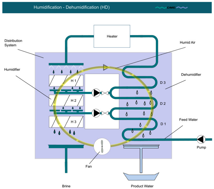
Fig. 3: Process scheme of HD plant with water (brine) extraction, adapted from [6].
Water Recirculation
The aim of an improved system with water recirculation is to minimise the thermal losses of a continuously operating HD plant. With a water recirculation system, the necessary heat as well as the temperature difference between the brine and the dry air at the humidifier entry can be reduced. Thus, entropy generation, or in simpler words further losses can be minimised [6]. Fig. 3 shows a sketch of the process.
In an ideally operated heat exchanger, the heat capacity rates on both sides of the heat exchanger should be equal and constant [28]. The heat capacity rate is the product of the mass flow rate and the heat capacity and therefore a key figure for the transported enthalpy of a medium in a heat exchanger. This is not the case in a single-stage humidifier and dehumidifier. First of all, for both air and water flow, there is a weak dependency of the heat capacity cp on the local temperature at a certain position in the humidifier or dehumidifier. However, this effect is only of minor significance. More important is the fact, that due to the on-going evaporation and condensation of pure water in the humidifier/dehumidifier, the mass flow rate of both air and water (feed or condensate) is strongly varying from in- to outlet. To take the humidifier as an example, the feed water flow is “losing” up to 7 % of its mass flow rate from humidifier inlet to outlet (see also chapter 1 – “Process Requirements/Peculiarities”). On the other hand, the air mass flow rate is enriched by the same amount of pure water vapour [46]. According to heat exchanger theory, see Annex E1, this leads to large temperature differences between humid air and feed water over the length of the heat exchanger. Large temperature differences inevitably result in entropy generation, which means a systematic reduction of efficiency in any heat exchanger [6, 28].
An efficient way to overcome this problem is to split up both humidifier and dehumidifier in several stages and to adjust either the feed water (“water recirculation”) or the humid air mass flow (“air recirculation”) in every stage to its optimum. In this context, the term “stages” stands for several “effects” and describes the core of a Multi-Effect Humidification (MEH) system.
Fig. 4 shows temperature profiles of water and humid air in the humidifier (H) and dehumidifier (condenser, (C)). On the top, temperature profiles over heat exchanger length in a single-stage setup as shown in Fig. 2 are given. On the bottom, temperature profiles of a three-stage setup as shown in Fig. 3 and 5 are outlined. It becomes obvious that with controlled heat capacity rate in every stage, the temperature differences between water and humid air can be minimized. It is interesting to see how the required heat input (red arrows in Fig. 4) for heating the feed water to TBT can be reduced by minimising the temperature differences between water and humid air. To reduce the heat input means at the same time to enhance PR.
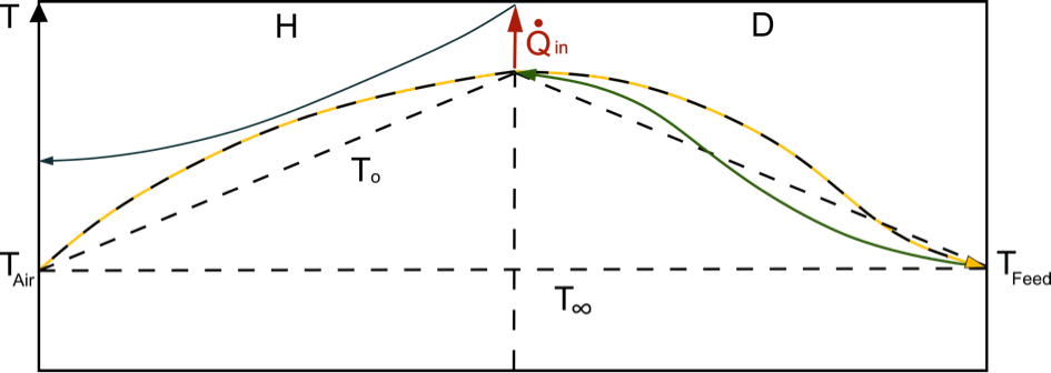
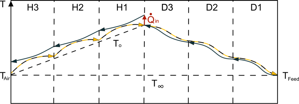
Fig. 4: Temperatures (T) of air and feed in an HD-plant without water recirculation (top) and with water recirculation (bottom), adapted from [6]. (H) shows a single-stage humidifier, H1, H2, H3 a three-stage humidifier from top (1) to bottom (2). (D) analogously for the dehumidifier with (1) bottom and (3) top. T0 would be the theoretical temperature profile without mass transfer. T∞ is the ambient temperature. Note the lower heating power requirements in the staged MEH configuration.
With water recirculation as shown in Fig. 3, the heat capacity flow of the feed water is adjusted to the heat capacity flow of the carrier medium humid air by means of adjusting the feed mass flow. The brine that is not necessary to heat up the air in the humidifier is used to preheat the feed water in the dehumidifier [6, 29]. However, Narayan et al. [29] found, that balancing of the dehumidifier leads to better process efficiencies than balancing the humidifier.
Air Recirculation
The aim of air recirculation is similar to the aim of water recirculation. The heat capacity flows of brine and air should be equal along the height of the humidifier [45]. The disadvantage of air recirculation is to handle the control of the air flow properly. In any case, this cannot be achieved by natural convection [6]. Additionally, the absolute humidity of the air in the bypasses is lower than the humidity in the air that passed the complete humidifier. This leads to a lower condensate output [6]. A sketch of the process is shown in Fig. 5. A demonstration plant was realised in the late 1960ies by Hodges et al [14].

Fig. 5: Process scheme of an HD plant with air recirculation, adapted from [6, 14]
Multi-Stage Evaporation
A multi-stage evaporation strategy is especially suitable for air heated systems in order to increase the moisture of the air entering the dehumidifier by several subsequent heating and adiabatic humidification steps. The aim of this multi staging is to reduce the necessary air flow by optimizing its humidity. In this kind of multi- stage evaporation, several humidifiers are switched in series and supplied by one single feed mass flow at TBT. The process is analogue to advanced solar drying processes, e.g. in large solar tunnel dryers.
Similar to evaporative cooling, in adiabatic humidification, the temperature of the air decreases due to the necessary heat of evaporation. A further increase of the humidity seems not to be possible in the first step, since the relative humidity of the air tends towards saturation. In order to increase the absolute humidity of the air, it is therefore re-heated and passed to a subsequent following humidifier [6, 12]. However, multi-staging does not improve the performance of an air heated cycle significantly [28].
3. Feed Water
As already stated in chapter 1, HD is a relatively robust technique, where any kind of aqueous solution with vapour pressure of the components lower than that of pure water can be treated. Feed water needs to be coarsely filtered (particles larger than 1 mm diameter removed), and volatile components, such as some oils, solvents, alcohol, compounds of NH3 etc. need to be separated, which mostly means stripping before entering the actual HD system. Scaling plays no role in the humidifier, but has to be considered in dehumidifier, pipes and the distribution system in the humidifier. Thus, a minor amount of anti-scalants may be applied. As in HD most components can be built in plastic materials, corrosion normally is not an issue [5, 13, 37].
Concerning salinity of the solutions, no restrictions do exist, unless the crystallization limits are reached. Thus, ZLD applications are possible. Exceeding the crystallization concentration limits may result in severe blocking of the humidifier outlet components [19]. However, due to the decrease in partial vapour pressure, note that the energetic performance of HD is dramatically reduced with increasing salinity [38].
The variety of feed waters treated in HD plants ranges from normal seawater, brackish water, industrial and organic waste water to very problematic substances like liquid manure from biogas plants [40, 44].
As energy input, low temperature heat is used from solar collectors, solar ponds, waste heat from industrial processes or generator sets. Furthermore, biomass or fossil fuel firing is possible. A minor amount of auxiliary electrical power is needed for running pumps, fans and control devices.
| Feed Water Salinity | Technically feasible | Now in Use for Desalination | Potentially for techno-commercial Viability for the Future |
|
> 100,000 ppm |
X | ||
|
50,000 – 10,0000 ppm |
X | ||
|
10,000 – 50,000 ppm |
X | ||
|
1,000 – 10,000 ppm |
X | ||
|
< 1,000 ppm |
Table 1: Stage of development of HD technology in relation to water salinity
4. Desalinated Water & Brine
As long as no compounds with vapour pressure lower than water are contained in the feed water, the product water is of highest quality distilled water. Minor contaminants may be induced to the condensate via the air flow, but this depends largely on the quality of the feed water [13].
As already mentioned, the product water is condensate, hence distilled water quality. Thus, it has to be remineralised and sterilised in order to provide it as potable water.
As the amount of chemicals needed for the operation of standard HD processes is very low, no contamination of the brine has to be considered. The concentration of the brine depends on the operation mode (batch or continuous) and the Recovery Ratio RR. In continuous operation mode, the concentration is about 5 – 10 % higher than in the feed water.
5. Data and Information
Recovery Rate and Concentration Factor
The Recovery Rate (RR) depends on the operation strategy of the plant. If the brine is recirculated, RR is higher than in once-through operation. Li et al. [24] report an RR of 8 % while in a commercial ZLD plant of Terrawater GmbH an RR of 86% is reached in a batch process [42].
Generally, RR of HD-systems operated in continuous mode is much lower than for conventional systems, see chapter 1 “Process requirements”, what may lead to less effort in brine disposal [28].
The Concentration Factor (CF) consequently is a function of RR and can be described by
where mFeed is the feed water mass flow rate and mbrine,out is the brine (= concentrate) mass flow rate leaving the system.
Specific Energy Consumption SEC (Energy per m3 Output)
The Specific Energy Consumption (SEC) depends mainly on the plant configuration (see chapter 2), the operation mode (Performance Ratio PR vs. output), the recovery of the latent heat of evaporation and the vapour pressure difference between air and water phase in the humidifier. The PR varies between 4.5 and 1.2 for HD-plants, what is equivalent to a Specific Energy Consumption of 140 – 550 kWh/m3 [28, 37]. Auxiliary power requirements are very low.
Chemical Additive Consumption
Chemical additive consumption is very low. A small amount of anti-scalants may prove useful, while practically no anti-corrosives, anti-fouling, etc. are needed [13].
Personnel Intensity
The personnel intensity is largely depending on the plant configuration. For single-stage once-through HD, the plants are self-content with only a very small amount of maintenance. They can be handled by shortly introduced but otherwise unskilled staff. [13]
However, a higher grade of complexity is reached with multi-stage plants (brine/air recirculation or multi-staging, see Fig. 3 to 5). Due to their higher control effort, they include more complex components. Hence, these configurations need to be run and maintained by technically trained staff.
Replacements
Again, it is important to point out the robustness of HD systems, which means that the need for replacements is comparatively low. Note that the requirements depend on the quality of the feed. With problematic feed water, there is certainly a need for regularly replacing the packing material. If sponge balls are applied for cleaning the dehumidifier tubes, they also have to be replaced periodically [13].
6. Preferred Use
As in HD, the requirements for feed water quality are rather low, the preferred fields of use are manifold. From the classic applications in the production of potable water in the public or private sector, further fields of use lie in the treatment of industrial waste water (whenever waste heat is available) and agricultural applications like the treatment of liquid manure [40, 41, 42].
As already described, the classical purpose of HD is the production of potable water. Note that HD (along with Mechanical Vapour Compression MVC and (Vacuum) Membrane Distillation (V)MD) is one of the few desalination technologies capable for ZLD applications. Accepting a higher SEC at increased salinities, HD can easily go up to the crystallization limits of seawater [19]. One application could be a higher concentration of brine from a Reverse Osmosis (RO) plant in a ZLD configuration. With such “hybrid” RO-HD systems, the amount of brine to be disposed to the environment can be reduced while the product water output can be increased.
However, in many industrial and agricultural applications, a major goal is to reduce the amount of waste water and thus reduce costs for their disposal. Here, the actual product is not the condensate, which in most cases can be recycled to the production process, but the concentrated brine. One example is the treatment of liquid manure from biogas plants, where concentration factors of up to a factor of 10 are possible. In this case, a welcome by-product would be the condensate containing a high amount of NH3, which can further be used for the production of fertilisers [40, 44].
Another field of application that is becoming more and more important is the mining industry. Here, the treatment of waste water from hydraulic fracturing processes seems to be an attractive application [11].
It has to be said, that for standard seawater desalination in drinking water purposes, HD rarely is economically viable. The main reason for that is its high energy consumption compared to Reverse Osmosis (RO) and its large installation space requirements. Therefore, the application of HD is mostly restricted to special industrial and agricultural water treatment tasks. However, its application for potable water production can be economically viable in remote areas with low infrastructure and no skilled staff available [13, 26, 37]. In the last case, especially the application of Solar Stills (see chapter 2 – “HD System Configurations”) as a special form of HD systems might also prove feasible.
7. Einvironmental Impact
When driven with fossil fuels, which is the case only for a few special applications, HD has a high environmental impact due to its high Specific Energy Consumption SEC. The impact due to brine disposal depends on the application and the Recovery Ratio RR. It goes without saying, that brine disposal becomes more difficult with high concentration rates. Anyway, this is the same issue as in any other thermal desalination system.
Generally, it can be said that compared to other thermal processes, brine disposal is less problematic, as the use of chemicals is very limited. Furthermore, hardly any metal heat exchangers are applied, so the output of heavy metals to the marine ecosystems is quasi nil. Chlorination of the feed or balancing of the pH-value is not required in HD. For the whole complex of environmental problems, see [23].
8. Stage of Maturity
| 1 | 2 | 3 | 4 | 5 |
| Basic R&D |
Prototyping/ |
Field Tests/ Demonstration |
Commercialization (up to seven years) | Use/Established (more than 7 years) |
| X |
Table 2: Stage of maturity of MDC technology
9. Further Developments
As HD plants for laboratory purposes can be built up quite easily and with a comparatively small budget, a huge amount of experimental and numerical university-based research was already performed and is still going on. Especially desalination groups in developing countries are interested in the technology and try to achieve either cost reduction or efficiency improvements. A special focus lies on the application of solar thermal collectors to provide the necessary energy requirements. In this context, the Solar Still is one of the most popular topics in low- budget desalination research with roughly 150,000 publications during the last ten years.
Challenges for Improvement
Challenges for improvement certainly lie in the development of multi-stage plants, where the main goal is a reduction of the Specific Energy Consumption SEC. Especially in systems with air or brine recirculation, control problems are a main issue [2]. Currently, much work is done on the improvement of the humidifier. For very problematic feed water, technologies like bubble columns are coming up, especially in the field of treating water from hydraulic fracturing [11, 17, 37].
What is being worked/researched on?
In the HD area, research is still done on the issues mentioned above: multi-staging, control problems in air- or brine recirculation and optimisation of bubble columns. [15, 34, 37]. More work is done on optimised operation strategies in special applications like ZLD, dealing with very high concentration rates [19]. In the field of concentrating liquid manure, work is done on the optimal extraction of NH3 to the condensate [44]. A special focus in the solar field is still lying on the improvement of Solar Stills [16].
10. References
[1] Abdelmoez, W., M. S. Mahmoud, M. S., Farrag, T. E., Water desalination using humidification/dehumidification (HDH) technique powered by solar energy: a detailed review, Journal of Desalination and Water Treatment, 2014, pp. 4622-4640.
[2] Al-Enezi, G., Ettouney, H., Fawzy., N., Low temperature humidification dehumidification desalination process, Journal of Energy Conversion and Management, 2006, pp. 470-484.
[3] Al-Hallaj, S., Farid, M. M., Tamimi, A. R., Solar desalination with a humidification-dehumidification cycle: performance of the unit, Desalination, 1998, Volume 120, pp. 273-280.
[4] Ben Amara, M., Houcine, I., Guizani, A., Maalej, M., Experimental study of a multiple-effect humidification solar desalination technique, Desalination, 2004, Volume 170, pp. 209-221.
[5] Bourouni, K., R. Martin, Tradist, L., Chaibi, M. T., Heat transfer and evaporation in geothermal desalination units, Journal of Applied Energy, 1999, pp. 129-147.
[6] Brendel, Th., Solare Meerwasserentsalzungsanlagen mit mehrstufiger Verdunstung, Dissertation, Ruhr-Universität Bochum, 2003.
[7] Chafik, E., A new type of seawater desalination plants using solar energy, Desalination, 2003, Volume 156, pp. 333-348.
[8] Chafik, E., Design of plants for solar desalination using the multi-stage heating/humidifying technique, Desalination, 2004, Volume 168, pp. 55-71.
[9] El-Agouz, S. A., Abugderah, M., Experimental analysis of humidification process by air passing through seawater, Journal of Energy Conversion and Management, 2008, pp. 3698-3703.
[10] Farid, M. M., Al-Hajaj, A. W., Solar desalination with a humidification-dehumidification cycle, Desalination, 1996, Volume 106, pp. 427-429.
[11] Gradiant Corp., Technology Sheet - Carrier Gas Extraction, 17.11.2017, gradiant.com/technology/carrier-gas-extraction
[12] Hassabou, A. H., Spinnler, M., Polifke, W., The role of conductive packing in direct contact regenerators within humidification-dehumidification cycles–part II: Experimental analysis, International Journal of Advanced Research in Engineering and Technology (IJARET), vol. 5(12) (2014), pp.97-106.
[13] Heyn, N., Terrawater GmbH, phone conversation on November 13th, 2017
[14] Hodges, C. N., Thompson, T. L. , Groh, J. E., Sellers, W. D., The Utilization of Solar Energy in a Multiple-Effect Desalinization System, Journal of Applied Science 3 (1964), pp. 505–512.
[15] Joffe, J., Boiling-point elevation,Journal of Chemical Education, 1945, pp. 270 ff.
[16] Kaushal, A., Solar stills: A review, Renewable and Sustainable Energy Reviews, Volume 14, Issue 1, January 2010, Pages 446-453.
[17] Khalil, A., El-Agouz, S. A., El-Samadony, Y. A. F., Abdo, A., Solar water desalination using an air bubble column humidifier, Desalination, 2015, Volume 372, pp. 7-16
[18] Khedr, M., Techno-economic investigation of an air humidification-dehumidification desalination process, Journal of Chemical Engineering Technology, 1993, pp. 270-274
[19] Kiefer, F., Schummer, F., Präbst, A., Spinnler, M., Sattelmayer, T., "Optimization of a multi-effect vacuum membrane distillation system for highly concentrated aqueous electrolyte solutions in liquid desiccant air conditioning and zero liquid discharge, Desalination for the Environment: Clean Water and Energy, Rome 2015
[20] Kiefer, F., Spinnler, M., Sattelmayer, T., Experimentelle und theoretische Untersuchungen zu einem hocheffizienten solarbetriebenen Klimatisierungsverfahren auf Basis flüssiger Sorbenzien – Solar Powered Air Conditioning Efficiency (SPACE), Final Project Report for Project Nr. 01DH13019 funded by the German Federal Ministry of Education and Research, Munich, 2017
[21] Klausner, J. F., Mai, R., Li, Y., Innovative freshwater production process for fossil fuel plants, U.S. DOE - Energy Information Administration annual report, 2003.
[22] Kroiss, A., Praebst, A., Hamberger, S., Spinnler, M., Tripanagnostopoulos, Y., Sattelmayer, T., Development of a seawater-proof hybrid photovoltaic/thermal solar collector, International Conference on Alternative Energy in Developing Countries and Emerging Economies, 2013.
[23] Lattemann, S., Development of an environmental impact assessment and decision support system for seawater desalination plants, Dissertation, Delft University of Technology, Delft, 2010.
[24] Li. Y., Klausner, F., Mai, R., Performance characteristics of the diffusion driven desalination process, Desalination, 2006, Volume 196, pp. 188-209.
[25] Minier-Matar, J., Sharma, R., Hussain, A., Janson, A., Adham, S., Field evaluation of membrane distillation followed by humidification/dehumidification crystallizer for inland desalination of saline groundwater, Desalination, 2016, Volume 398, pp. 12-21.
[26] Müller-Holst, H., M. Engelhardt, M. Herve, und W. Schölkopf. „Solarthermal seawater desalination systems for decentralised use.“ Renewable Energy, 1998: 311-318.
[27] Müller-Holst, H., Schölkopf, W., Thermally Driven Sea Water Desalination using the multi effect humidification dehumidification method, Proceedings of the ISES Solar World Congress, 2001, pp. 883-891.
[28] Narayan, G. P., Sharqawy, M. H., Lienhard, J. H., Zubair, S. M., Thermodynamic analysis of humidification dehumidification desalination cycles, Desalination and Water Treatment, 2010, pp. 339-353.
[29] Narayan, G. P., Summers, E. K., Zubair, S. M., Antar, M. A., Lienhard, J. H., Sharqawy, M. H., The potential of solar-driven humidification-dehumidification desalination for small-scale decentralized water production, Renewable and Sustainable Energy Reviews 14.4, 2010, pp. 1187-1201.
[30] Narayan, G. P., McGovern, R. K., Lienhard, J. H., Zubair, S. M.,Helium as a carrier gas in humidification dehumidification desalination systems, Proceedings of ASME 2011 International Mechanical Engineering Congress & Exposition IMECE 2011 November 2011, Denver, USA.
[31] Nawayseh, N. K., Farid, M. M., Al-Hallaj, S., Al-Timimi, A. R., Solar desalination based on humidification process - I. Evaluation the heat and mass transfer coefficients, Energy Conversion & Management, 1999: 1423-1439.
[32] Orfi, J., Laplante, M., Marmouch, H., Galanis, N., Benhamou, B., Nasrallah, S. B., Experimental and theoretical study of a humidification dehumidification water desalination system using solar energy, Desalination, 2004, Volume 168, pp. 151-159.
[33] Polifke,W., Kopitz, J.,Wärmeübertragung: Grundlagen, analytische und numerische Methoden, Pearson Studium, 2nd edition 2009, ISBN-13: 978-3827373496.
[34] Prakash, S., Shannon, M., Bellman, K., Water Desalination: Emerging and existing Technologies, in: Aquananotechnology: Global Prospects by Reisner, D.E., Pradeep, T., CRC Press, 2014, pp. 533-562.
[35] Reid, R. C., Prausnitz, J. M., Poling, B. E., The properties of gases and liquids, McGraw-Hill, Boston, 2001.
[36] Seifert, B., Schaufuss, P., Spinnler, M., Sattelmayer, Th., CFD-simulation of a humidification-dehumidification desalination plant for transient solar irradiation, IDA World Congress, Dubai, 2009.
[37] Seifert, B.,P erformance improvements of humidification-dehumidification desalination systems with natural convection, Dissertation, Institute of Thermodynamics, Technical University of Munich, 2017.
[38] Sharqawy, M. H., Lienhard, J. H., Zubair, S. M., The thermophysical properties of seawater, Journal of Desalination and Water Treatment, 2010, pp. 354-380.
[39] Spinnler, M., Seifert, B., Kroiss, A., Kiefer, F., Desalination, material to the lecture “Desalination”, Institute of Thermodynamics, Technical University of Munich, 2017
[40] Terrawater GmbH, terraorganic – Technical Description, last access: 28.02.2019, www.terrawater.de/terra-organic-beschreibung
[41] Terrawater GmbH, TerraPreCon – Technical Description,last access: 28.02.2019, http://www.terrawater.de/terraprecon-beschreibung
[42] Terrawater GmbH,TerraSaline 3.5/7.0 Datasheet, Kiel, 2015.
[43] Tow, E. W., Lienhard, J. H., Heat flux and effectiveness in bubble column dehumidifiers for HDH desalination, World Congress on Desalination and Water Reuse, Tianjin, 2013.
[44] Ugresic, V., Spinnler M., Development of a liquid manure processing plant on the basis of the humidification dehumidification process, Final Report to Project Nr. KF 060810 RH8 in the PRO INNO II program of the German Federal Ministry for Economic Affairs and Energy, Munich, 2009.
[45] Whitefield, S., Treatment of highly concentrated salt solutions in industrial and mining applications, Society of Petroleum Engineers, 2015, last access 22.08.2016.
[46] Younis, M. A., Darwish, M. A., Juwayhel, F., Experimental and theoretical study of a humidification-dehumidification desalting system, Desalination, Volume 94, 1993, pp. 11-24.